Control light & fans with same PCB?

Hello DIY friends,

I am not an electrical engineer so I do not understand much about and it lacks on the basics. I’m running mycodo pretty long it is working stable. Thank you Kyle!

Now to my question. I have 3 different PCB’s for 3 different PWM scenarios (Meanwell LED Driver, Duct Fan, PC Fan). From what I understood this is because e.g. Meanwell brings it’s own voltage on the Dim+ lane. The 2 fans I have not. Because of that I tried find a workaround by using a 0-10V converter. But this somehow is not fully controlling the devices from 0-100%.

Can anybody of you clever minds help me out and knows a PWM converter standard for every light/fan scenario in the world that allows full 0-100% control from 3.3v Raspberry or is this simply physically not possible?
Because some supplier use different electrical designs?

Thank you in advance! You would help me a lot I am just not getting the solution with my own research.

Regards
OjunbamO

Lights and fans usually use different PWM frequencies and different operating voltages.

Computer fans usually use 12v - this may be one reason why you are not getting 100% from your 10v converter. Also, 4-wire computer fans have their own PWM controller built-in, so you don’t need this converter board.

Duct fans can use many different voltages and different kinds of motors. The DC ones I’ve seen can use 10, 12, 24, and even 48 v DC. So again, if your duct fan needs more than 10v, you will never get 100% speed from it by powering it with a 10v converter. Also, a lot of duct fans run on AC, not DC, and you can not use PWM to control AC power at all. There are also EC type motors, those usually come with their own speed controller. Do you know what kind of motor your duct fan has and what voltage it needs?

Where is that 10v PWM converter getting it’s power from? What kind of power supply are you feeding it voltage from? How many volts? How many Amps?

There really is no “universal voltage or PWM frequency for every fan and light in the world”. You really should power each device with it’s own dedicated power supply and each with it’s own PWM input.

That PWM board you posted requires a minimum of 4.5v PWM input signal. The Raspberry Pi only outputs 3.3v max on it’s GPIO… so you would probably need a level shifter in between the Pi and your PWM board to bring the signal from 3.3v up to at least 5v. That board also says it needs a 1 kHz to 3 kHz PWM input signal… did you set that PWM output frequency in your Mycodo PWM module?

First thank you for the detailed answer it helped me again a lot for my understanding.

For the frequency i kept it between 1-3k when using the board (if I remember correctly 1k worked best).

The board is getting powered by a separated power supply with 10V 1A (link). I didn’t even know that the converter board only works with +4,5v input signal. That would explain why the lamp was not getting fully controlled to 100%. Will need to try this :smiley:

Yea so I thought that 90% of common devices are using 10V PWM input. At least all of the duct fans I saw (4-8 inch of course not big industry ones or smaller sizes). And also all of the meanwell drivers had 10V? Getting a standard for those 2 devices would be already feasible.

So what I am interpreting now is that level shifting up to 4.5v and using the converter board is already the best solution in most of my cases? Or what do you think? :slight_smile:

Thank you!

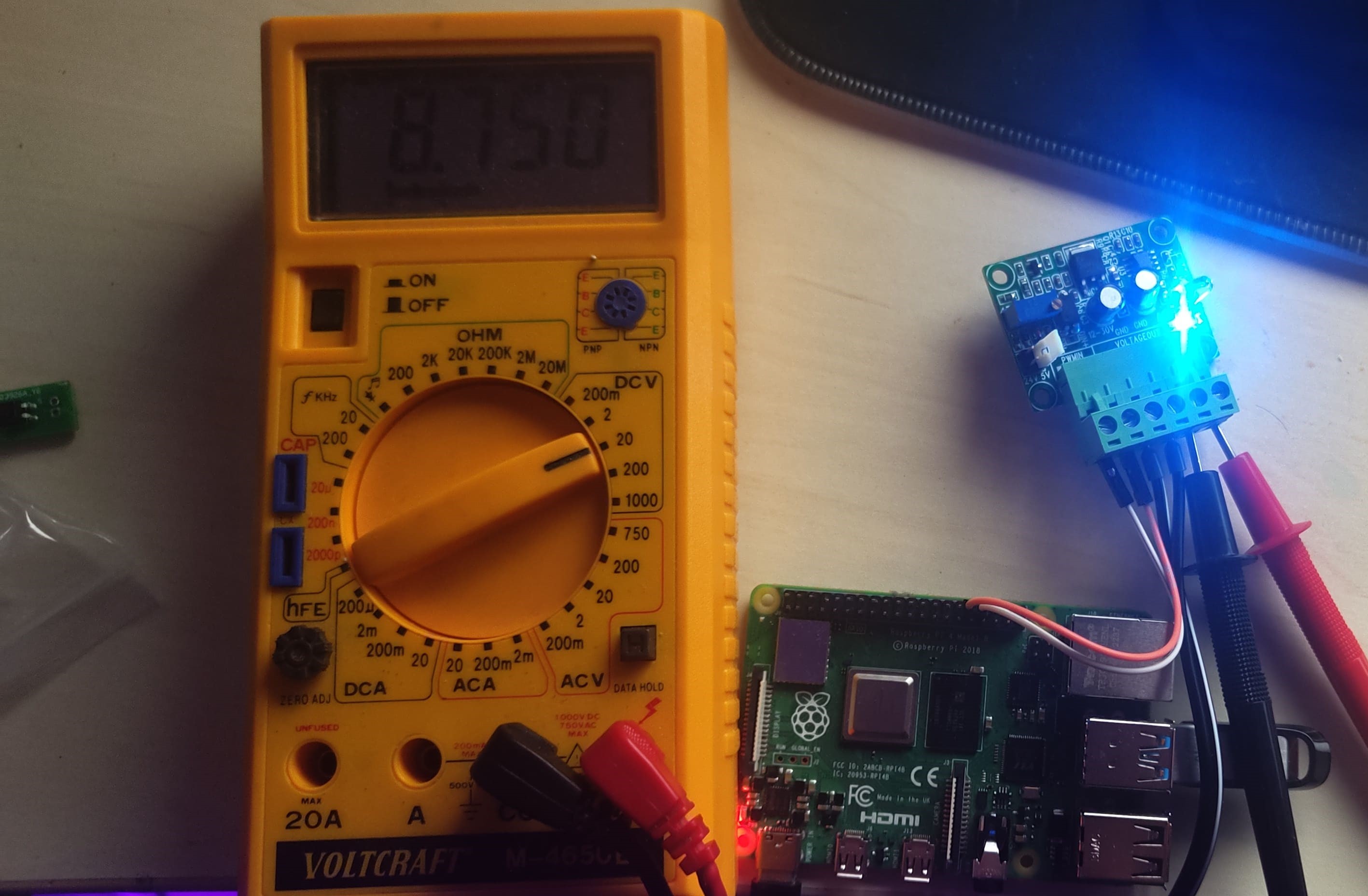
No, that doesn’t explain it… there are many factors that come into play here, the big one is that your little 1 amp power supply (PSU) that you are powering the PWM board with is WAY under-rated to drive LED grow lights. I’m surprised you didn’t burn it out just testing it. Look at your Meanwell drivers… what is the Output rating for the Amps? If you don’t understand the relationship between Amps, Volts, and Watts, I highly recommend you do some more reading or watch some youtube vids that explain basic DC electrical theory as well as Ohm’s Law (V=IR). In fact, I really recommend that you don’t go any further until you have a better understanding of electricity in general.
Seriously, I would not use those cheap Amazon PWM boards on your LED lights or with your Meanwell power supplies. Meanwell (and many other LED power supplies) already use built-in “constant voltage PWM” to drive the lights as bright as they can go, without burning them out, while also reducing their waste-heat output. If you alter that PWM frequency or add another PWM signal on top of the PWM signal those drivers are already using, you could burn out your Meanwell drivers or your LEDs. If you power your 10v LEDs with a non-PWM straight 10V DC current, you will likely burn out your LEDs or drastically shorten their lifespan, because they will run too hot, while also looking too dim. PWM isn’t just used to dim LEDs it is also used to over-drive LEDs to make them brighter than they would be by just using straight non-modulated current.

Personally, I don’t think there is any reason to dim LED lights. If your plants are showing signs of light burn, simply raise the lights a few inches away from the plants, or use fewer lights until the plants are mature enough to handle full light. If you feel like you need to dim your lights, I would buy a Meanwell power supply that is dimable, and make sure it is compatible with your lights (correct Voltage and Amperage). In fact, you may want to closely inspect the Meanwell drivers you already have, they might already have their own input for an external PWM signal so you can dim them.

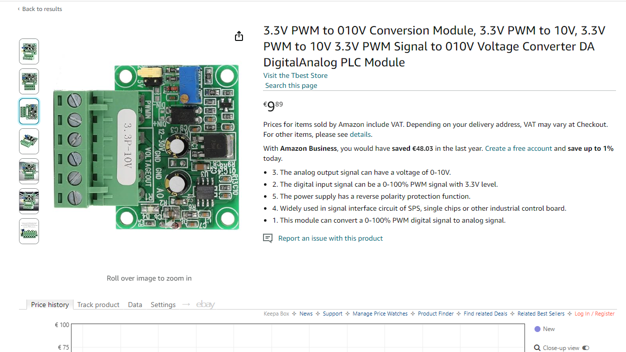
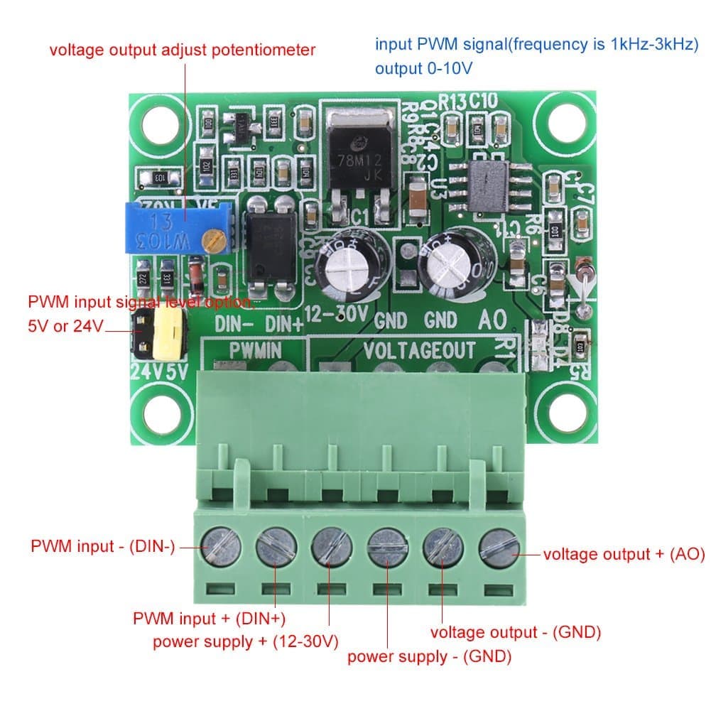
No, it is not the best solution. In fact, I would actually just throw those 10v PWM boards in the trash. They are useless… look at their power rating… only 12 milliamps! That’s barely enough to power a single small computer fan, and it’s the wrong voltage! And the PSU you are running them from is only 1 amp, which means it might be able to handle a 0.5 amp constant load without overheating and burning out. 10v is just not a very common voltage for devices to run on. If you are absolutely sure your duct fan is a 10v DC motor (which I highly doubt) then you would need a MUCH larger PSU.

Absolutely not, there is no “standard voltage” that you can run everything on, so get that idea out of your head. Every device will need it’s own voltage and draw it’s own amperage, therefore every device needs it’s own properly matched power supply. If you try to power a device with a lower voltage, or not enough amperage, you will either damage the device, or burn out the power supply, or even start a fire. Also, trying to run all of your devices from one big power supply might seem like a more efficient way to go, but in reality, you are better off with a PSU for each device… if your one big PSU dies, your whole system is down… if you have several devices all with their own PSUs, at least part of your system will still function until you can replace the bad PSU.

Not sure where you are looking at Meanwell drivers, but most of their drivers I’ve seen come in 12, 24, 36, 48, and 52 volt versions but I don’t see any 10v ones? You may want to post a picture of your meanwell driver’s spec label.
The most common DC voltages are usually multiples of 1.5, 1.2, or sometimes 2.1 volts… because those are the voltages most commonly found in single-cell batteries. Also, most DC devices do not use PWM, they use straight, non-modulated, DC current.

Thank you again for your time.
Yea I guess if I would have that technical ground knowledge this thread wouldn’t exist. Do you have any recommendation for a good read or youtube channel?

Except that you already answered more than I could have asked :smiley: I am just linking this now because your last paragraph confuses me completely. So yea my driver runs at 12-24V 240W. The dimming operation part of the datasheet is saying it is using 10V PWM? The same goes for page 27 on my fan 0…10V/PWM .

So yea I have to learn a lot about it, very interesting and cool stuff that is possible.
I only thought the difference is that the led driver brings constant power outage on dim+ port and the fan on 3nd separated port and I could get it working with the same PCB. But if you say there is much more behind it and each device needs it’s own individual solution I have to accept that :confused:

It would have been much more useful to help you if you had posted your manuals in the first place.

Ok, so you are talking about using 10V dimming signal. As described on Page 4 of your Meanwell driver manual. Would have been really helpful to know that from the start since you really didn’t explain this very well in your first post.
So according to the Meanwell manual, you can do 3 types of dimming signal on that driver to control the LED output.
10v PWM input signal (additive PWM)
0-10V straight current input signal (additive voltage)
add a 100 kΩ potentiometer across the dimming inputs (additive resistance)

This means that your PWM boards should actually work for dimming your meanwell driver,
The only problem is that those PWM boards you have look like they are the wrong logic level voltage (4.5 or 24V???). That means they might not work with the raspberry pi’s 3v3 logic level. Instead of buying level shifters, which would be more expensive and more complicated, I would recommend buying different PWM converter boards that are 3v3 compatible. Also, those converter boards need a 12-30 volt power supply to power them, so the “10v” power supply you were using is actually adjustable and should be set to 12V to power those boards… and each PWM board will need it’s own power supply… which is starting to get even more complicated. I would first try setting your adjustable power supply for the PWM board to 12v and then connecting it to the Pi for PWM input… and then testing the PWM board’s output voltage with a multimeter (VOM) and see if you can get the full 0-10v range out of it after powering with 12v. It may work… but If not it may be due to the logic level not being compatible.

Your fan is an EC fan… that would have been useful to know from the start as well. So it looks like the fan manual says the speed is controlled with a 0-10v signal. So again, these PWM converters look like they will work, except for having the wrong logic level to be compatible with the raspberry pi and the fact that you said you were under-powering them at 10v instead of the 12v-30v they require.

Ok so my understanding wasn’t completely wrong and it is possible. Sorry for not clarifying it. Like I said I thought 0-10v PWM is the standard for dimming most common devices that’s why I thought you know what I am doing.

Just searched a bit around the web and those chinese boards are always the same like the ones I have. The one I bought said it can switch 3.3v PWM (or I didn’t read correctly and the 3.3V level stands for level shifting) but when you look on the pictures like the one you sent it is requiring +5v… So I got scammed :smiley:

Let me know if you found by any chance a converter board working with 3.3v PWM otherwise for now I will try level shifting.

Again I can’t thank you enough for the input you gave me already!

There are many boards that advertise 5V or 3.3V but are compatible with both. This board converts a 3.3/5 VDC PWM input signal unto a 0 - 10 VDC output. Just use a multimeter to see if the output is 0 VDC when sending it a 0 % duty cycle and 10 VDC when sending 100 %.

1 Like

I’m sorry or all the confusion… I think this is one of those lost-in-translation situations :face_with_diagonal_mouth: . Like I said, and like Kyle said… it will probably work with the Raspberry pi’s 3.3v, but the problem you were most likely having was you said you were only powering the PWM board with 10v when it needs at least 12v to operate properly. That wall adapter you posted the link to is adjustable, what voltage did you have it set to when you were testing these PWM boards?

Thank you guys I thought in the meantime I am completely stupid.
Just found the time to test out what Kyle wrote and the multimeter is saying 8.7v (100% PWM) when using frequency of 1k and 12v 1A power supply that I linked some comments ago.
The power supply directly connected to multimeter it is saying 12.0v so power supply is working.

Anybody an idea what I could have done wrong? Otherwise I think I will again need to find a different circuit… :confused:

EDIT: btw the circuit is coming directly out of the anti-static plastic packaging

Ok… now that you have everything hooked up, and you are sure that you are sending a 100% PWM signal from your Pi, next you will need to calibrate the “voltage output adjust potentiometer” to adjust the output voltage of the PWM board to exactly 10V. Do this while it is hooked up and everything is running so you can watch the VOM. Any time the input voltage to the PWM board changes, the output will likely change as well. So this calibration step should be done any time you change the power supply on the PWM board to ensure the output of the PWM board is exactly 10v, even if a new power supply you switch to says it is 12v, there could be slight variation that will change the output of the PWM board.

yea so I turned it up the maximum but still only at 8.9v (it is making click sounds when trying to increase further and it’s adding not more) :confused: lowest is 5.4v so I think this was the maximum

First try changing the PWM frequency on the Pi to 3 kHz.
Then try one of your other PWM boards to see if they are all having this same issue.
If that doesn’t change anything, then you may need to try a different power supply for the PWM board. I’d try at least 18 or 24v.

yea so frequency is not changing anything on the voltage output.
Just ordered a different power supply will let you know :slight_smile: again thank you

1 Like

It might be that it actually needs a 5 VDC PWM input. Do you have a 5 volt microcontroller handy to flash a simple 100% duty cycle PWM output on a pin to test? You could also just connect any 5 VDC supply, since 100% duty cycle is literally always on.

Ok short update. Both scenarios work. But I would say using a input signal of 5v PWM & 12v is working more direct proportionale. When using 3.3v PWM and amplifying with 18v it is more fluctuating e.g.
30% PWM is ~4v
70% PWM ~7.8v
100% PWM ~10v
But still on a level where I say I could live with it. For anyone that was interested :slight_smile:

Again thanks. Learned a lot here! :smiley:

1 Like

Just out of curiosity, how are you generating a 5v PWM input signal?
Are you using an MCU with native 5v GPIO output like an Arduino, or are you using a level shifter in between the Pi and the converter board?
I would think that the 5v PWM input and the 18v power to the converter board would give you the most stable 0-10v output.

Ok yea I am again back trying because it showed on the multimeter 0-10v when using 3.3v PWM from the raspberry and 18v 1A power but the lights are not fully controllable somehow when pwm set to 0% they are still on :confused: I will try your suggestion with level shifting & 18v but I guess this is getting complex to get this board running…
Since I am not able to find a prebuild board with 3.3v PWM converting fully from 0 to 100% I am trying to rebuild something like the test circuits 2-3: https://www.reddit.com/r/AskElectronics/comments/52g76a/pwm_33v_to_010v_analog_converter/

I am not understanding why it is so hard to find a standard when both devices say they use 0-10v PWM :smiley: I thought when the multimeter says 0.014v (at 0% pwm) than the light should be off.
Random shot from me in the dark: can it be that the lamp reacts way more sensitive to created ripple than a duct fan does? Because it seems that the duct fan is getting controlled in every scenario very good. The light just doesn’t wan’t to accept a power source that is not coming from the dim+ lane on itself it seems. But I can control it for like 30-40%… :confused:

For more background these are the pcbs working for each device perfectly. I am trying to find 1 PCB working for both.


Personally I think there is no real point in dimming LED grow lights.
First of all, they don’t put out nearly the same PPFD as real sunlight, so dimming them is only going to deprive your plants of maximum PPFD energy and thus reduce growth potential.
If you are worried about light burn, then you are using too much light for your grow space, or your lights are too close to your plants. Simply use fewer lights or raise your lights a few more inches away from your plants.
If you really feel the need to dim your lights, there is no reason to do it remotely from Mycodo. Usually you are going to pick a setting and leave it there for weeks, like in the case of seedlings that may need less light (hint, they really don’t). So it’s better to get a LED driver with a dimmer knob, or in your case just put a 100 kΩ potentiometer across the dimming inputs and set the knob where you need it until your seedlings have more leaves and can handle full light.
If you are doing all this to simulate sunrise and sunset conditions, don’t bother. From the studies I’ve found that researched using simulated sunrise/set vs just turning the lights full on and full off, there was more growth observed using the full on full off method. Simulating sunrise/set only deprives plants of maximum potential DLI for a given lighting schedule.
The point of hydroponics is not to simulate natural conditions, but to go beyond natural conditions and provide a sustained state of precisely controlled homeostasis so that the plants can reach their maximum growth and yield potentials that they would otherwise rarely reach under natural conditions.

yea you are right. Currently I am mostly using the dimming operation for simulating sunrise/sunset which maybe brings no benefit.

However my plan in the future was to expand the system by some IOT devices that could control lights, ventilation system in my working place via homeassistant + mqtt. Apart I have said If I found the solution for pwm I also wanted to help some friends automating they’re systems. But if I don’t know for which devices it will work and for which not I will touch other lamps. :smiley: