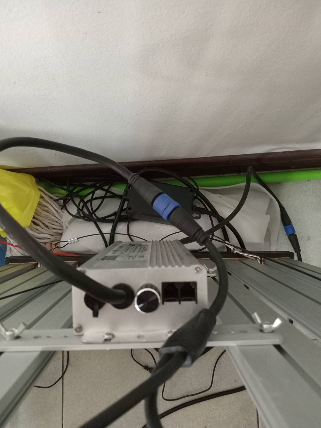
How do I have to wire up this LED psu to achieve intensity control via Mycode PWM?
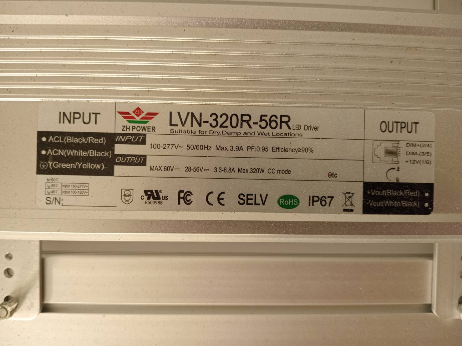
See the print on the case on the right side: inputs for dim + , dim -, and +12v.
The pi provides the PWM signal between one GPIO pin and ground.
How would I need to wire this up correctly?
Did your LED lights or the LED driver come with a manual?
Have you tried looking up or requesting the info on the manufacturer’s website?
You will need a manual or wiring diagram from the manufacturer to show you the actual wiring connections that you need in those RJ-11 connectors, otherwise you might damage your driver.
It looks like those drivers use the same method as a lot of drivers…
10v 0-100% PWM input signal (additive PWM)
0-10V straight current input signal (additive voltage)
or add a 100 kΩ potentiometer across the dimming inputs (additive resistance)
Your driver already has the 100 kΩ potentiometer for manual dimming, so why do you need to control it with the Pi? If you plan on simulating sunrise and sunset, it is completely unnecessary and has no positive effect on your plants, in fact it only deprives them of maximum DLI and reduces yields. Here is just one study that proves it…
https://www.researchgate.net/publication/336287076_Impact_of_a_shift_in_the_light_spectrum_on_lettuce_growth_Simulation_of_sunrisesunset_using_adjustable_monochromatic_LED_lights
Any “evidence” you might have seen to the contrary is most likely marketing and advertising lies from lighting manufacturers trying to sell you more expensive lights and drivers you don’t really need.
If you really need to dim your lights, like for seedlings, just use the already provided dimming knob, or simply raise your lights so they are not so close to your seedlings.
Either way, you can’t control dimming these lights directly with the Pi. You need an adapter board that converts the Pi’s 3.3v PWM signal up to 10v PWM or 10v straight DC current.
There is another post here where the person tried one of these adapter boards, but hasn’t been able to make it work, so I wouldn’t trust these boards.
These adapter boards also require their own separate power supply… which just makes your setup more expensive and more complicated… to do something you can already do with the knob on your driver.
https://www.amazon.com/s?k=3.3v+pwm+signal+to+0-10v+voltage+converter&crid=2LT4NDX808WB&sprefix=10v+PWM+converter%2Caps%2C133&ref=nb_sb_ss_ts-doa-p_2_17